Blog
How to Remove Schneider Contactor
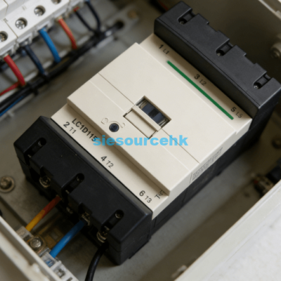
Learning how to remove Schneider contactor components is a fundamental skill for industrial maintenance. The process primarily involves releasing the mechanical locking clips and disconnecting the electrical terminals. Most Schneider TeSys D models, such as the LC1D50AF7, feature a spring-loaded mounting mechanism designed for 35mm DIN rails.
To begin the removal, you must first ensure all power sources are disconnected. Use a calibrated voltage tester to verify the absence of electricity across all poles. Once the system is safe, you can proceed to loosen the terminal screws. For the LC1D50AF7 model, these screws typically require a specific torque setting of around 5 N.m for installation, so they may be tight during removal.
After removing the wires, locate the plastic release tab at the bottom of the contactor. Insert a flathead screwdriver into the slot of this tab and pull it downward. This action retracts the internal spring, allowing you to pivot the contactor off the DIN rail. If the device is screw-mounted to a plate, you must remove the mounting screws located at the diagonal corners of the base.
Essential Safety Steps Before Removal
Safety is the most critical aspect of electrical maintenance. High-voltage environments pose significant risks if standard operating procedures are ignored. You must follow a systematic approach to prevent accidental energization or equipment damage.
Disconnecting Power and Lockout Tagout
Always perform a full Lockout/Tagout (LOTO) procedure before touching any wiring. Disconnect the main circuit breaker feeding the contactor and the control circuit. Place a physical lock and a warning tag on the power source. This ensures no other personnel can restore power while you are working.
Verifying Voltage with Multimeters
Never assume a circuit is dead just because a switch is off. Use a multimeter to check the voltage between phases and from each phase to the ground. Verify the multimeter on a known live source before and after testing. This double-check confirms the meter is functioning correctly during the test.
How to Remove Schneider Contactor from DIN Rail
The TeSys D series is designed for rapid installation and removal. The mechanical design focuses on a “clip-on” system that secures the device to a standard 35mm rail. Understanding the geometry of this clip is the key to a smooth removal process.
Identifying the Spring-Loaded Clip
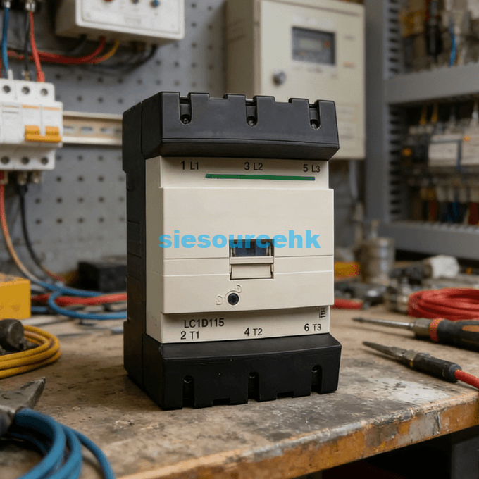
Every Schneider TeSys D contactor features a black or grey plastic slider at the bottom center. This slider is connected to a heavy-duty internal spring. This spring provides a clamping force of approximately 10 to 15 Newtons to keep the device stable. You can see the small rectangular opening designed for a screwdriver head.
Releasing the Wire Terminals Correctly
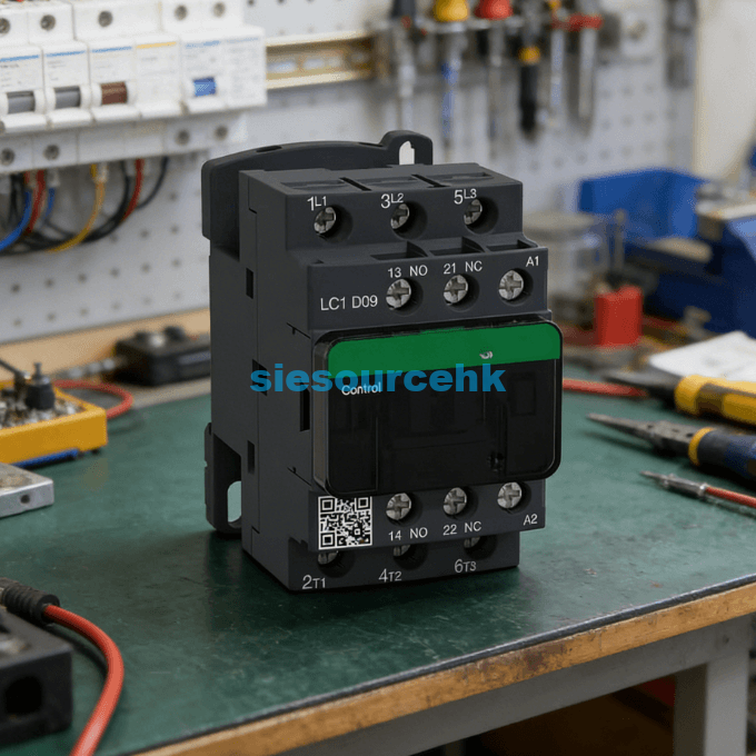
Schneider uses different terminal technologies depending on the contactor size. Smaller units use standard screw clamps, while larger models like the LC1D50AF7 utilize EverLink BTR screws. Use a Pozidriv No. 2 or a flathead screwdriver to loosen these. Ensure you label every wire with its corresponding terminal number to prevent wiring errors during replacement.
- Loosen the control circuit wires connected to terminals A1 and A2.
- Unscrew the power cables from the main poles (1L1 through 6T3).
- Pull the wires clear of the contactor body to create space.
- Insert the screwdriver into the bottom release tab slot.
- Lever the tab downward while pulling the bottom of the contactor forward.
- Lift the contactor upward to unhook it from the top edge of the DIN rail.
Detailed Mechanical Disassembly Procedures
When dealing with larger industrial units, the weight of the device can exceed 1.5 kilograms. This weight requires a firm grip during the mechanical release phase. Improper handling can lead to dropping the unit and damaging neighboring components.
Managing Heavy-Duty EverLink Terminals
The EverLink BTR screws found on the LC1D50AF7 provide a constant tightening pressure. This technology helps maintain a low resistance of approximately 0.1 mΩ per pole. During removal, you might notice the screw resists more than a standard terminal. Use steady, even pressure to avoid stripping the screw head.
Handling Multi-Contactor Assemblies
In reversing starter configurations, two contactors are linked by a mechanical interlock. You must remove the interlock assembly before attempting to pull a single contactor off the rail. These interlocks usually clip into the side slots of both units. Carefully pry the interlock clip with a small flathead tool to separate the pair.
Removing Front-Mounted Accessories
Many Schneider contactors are equipped with auxiliary contact blocks or pneumatic timers. These must be removed before the main unit if space is limited. Most accessories are held in place by a simple latching mechanism on the front face of the contactor.
Detaching Auxiliary Contact Blocks
Front-mounted auxiliary blocks, such as the LADN series, have a small lever at the top. Push this lever toward the back of the contactor while sliding the block upward. This releases the hook that engages with the contactor’s moving core. Side-mounted blocks usually require a small screwdriver to release a side clip.
Disconnecting Suppression Modules
Surge suppressors or RC circuits are often clipped directly onto the coil terminals. These modules protect the control system from voltage spikes. To remove them, gently pull them away from the A1/A2 terminal area. Be careful not to bend the metal pins that insert into the screw clamps.
Identifying Signs for Component Replacement
Knowing when to remove a contactor is as important as the removal itself. Electrical wear on the contacts typically limits the service life. If you observe excessive heat or noise, it is time for a detailed inspection.
Inspecting for Contact Pitting and Discoloration
Check the plastic housing around the power poles for signs of melting or darkening. Contact resistance increases as the silver-alloy tips wear down. If the contactor makes a loud humming sound, the magnetic core may be dirty or misaligned. These physical symptoms indicate that the device has reached its end of life.
Evaluating Coil Resistance Failures
Use an ohmmeter to measure the resistance of the coil between A1 and A2. A healthy 110V coil for an LC1D50AF7 should show a specific resistance range noted in the manual. An infinite reading indicates an open circuit, meaning the coil is burnt out. A very low reading might suggest an internal short circuit.
Selecting a Replacement Schneider Contactor
When you remove a contactor for replacement, identifying the correct successor is vital. You must match the electrical ratings and the coil voltage exactly. For instance, if you are replacing a high-capacity unit, you might look at the Schneider Contactor LC1D50AF7. This specific model is a 3-pole device rated for 50A under AC-3 conditions.
Choosing a replacement requires checking the “AF7” suffix, which indicates a 110V AC coil. Installing a contactor with the wrong coil voltage can lead to immediate coil burnout or failure to pull in. You should also verify the “EverLink” terminal technology. This feature ensures constant pressure on the cables, which reduces the risk of overheating in high-current applications.
If your application involves frequent switching, look for devices with high mechanical durability. The TeSys D range is known for a lifespan of up to 15 million mechanical cycles. When evaluating your next purchase, consider whether you need built-in auxiliary contacts or if your environment requires a specific IP rating for dust protection.
| LC1D115F7 | LC1D115 | LC1D4011M5 | LC1D32AM7 |
| LC1D150F7 | LC1D128ED | LC1D128E7 | LC1D40AU7 |
| LC1D40AP7 | LC1D128E7 | LC1D128E7 | LC1D65M7 |
| LC1D40AP7 | LC1D95FE7 | LC1D38BL | LC1D32P7 |
| LC1D32P7 | LC1D5011E5 | LAD4RCU | LC1D115F7 |
| LC1D115F7 | LC1D8011M5 | LC1D150F7 | LC1D40AP7 |
Summary
To how to remove Schneider contactor units effectively, you must combine safety protocols with mechanical precision. The process involves de-energizing the system, disconnecting labeled wires, and using the bottom release tab for DIN rail detachment. Following these steps ensures the integrity of your electrical panel and the safety of the technician.
FAQ
1. What tools are needed to remove a Schneider TeSys D contactor?
You typically need a Pozidriv No. 2 screwdriver for the terminals and a medium-sized flathead screwdriver for the DIN rail release tab. For EverLink terminals on larger models, a 4mm Allen key may sometimes be required depending on the specific screw head.
2. Can I remove the contactor while the wires are still attached?
It is not recommended. Removing the contactor with wires attached can put undue stress on the cable lugs and the internal terminal housing. It also increases the risk of wires touching the metal backplate or other live components.
3. What should I do if the DIN rail clip is stuck?
If the plastic tab is brittle or stuck due to heat, do not force it excessively. Gently wiggle the contactor while pulling the tab. You may need to apply a small amount of non-conductive electrical cleaner to lubricate the sliding mechanism if it is seized by dust or corrosion.
4. How do I identify the coil voltage of a Schneider contactor before removal?
The coil voltage code is usually printed on the front face or the top side of the contactor near the A1/A2 terminals. For example, “B7” stands for 24V, “F7” for 110V, and “P7” for 230V AC. Always verify this before ordering a replacement.
5. Is the removal process different for LC1-D and LC1-E series?
While the general principle is the same, the LC1-E (EasyPact) series may have slightly different clip designs. Always check the specific manufacturer’s datasheet for the “E” series, as they are designed as a more economical, simplified version of the TeSys D line.