
Blog
How to Wire a Keyence Sensor
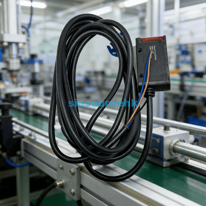
Wiring a Keyence sensor correctly is essential for maintaining the precision and longevity of your industrial automation system. Most Keyence models, including popular series like the FS, PZ, and specialized fiber optic units like the FU-97P, follow a standardized color-coding scheme. Typically, you will find three main wires: Brown for positive power (12-24V DC), Blue for negative (0V), and Black for the control output signal.
To successfully wire a Keyence sensor, you must first identify whether your system requires an NPN (Sinking) or PNP (Sourcing) configuration. This distinction determines how the load connects to the power supply and the sensor’s output wire. Miswiring these components can lead to short circuits or permanent damage to the internal circuitry of the sensor.
Understanding the Standard Color Codes and Pinouts
Most modern Keyence sensors adhere to the IEC 60947-5-2 international standard for industrial sensor wiring. Understanding these colors is the first step in any installation process.
The Three-Wire System
In a standard three-wire DC setup, each color serves a specific and non-negotiable purpose:
- Brown (V+): This wire connects to the positive terminal of your power supply, typically ranging from 12V to 24V DC.
- Blue (0V/GND): This connects to the negative terminal or common ground of the power supply.
- Black (Output): This is the switching signal wire that connects to your PLC input or relay coil.
Specialized Four-Wire Systems
Some advanced Keyence sensors feature a fourth wire, usually White or Pink. These are often used for “Control 2” outputs or “Remote Teach” functions. In these cases, the white wire might act as a normally closed (NC) output, while the black wire remains the normally open (NO) output.
How to Wire NPN vs. PNP Keyence Sensors
The choice between NPN and PNP wiring usually depends on the regional standards of your PLC or control system. North American and European markets predominantly use PNP, while NPN remains common in parts of Asia.
Wiring an NPN (Sinking) Sensor
In an NPN configuration, the sensor “sinks” the current to the ground when triggered. To wire this correctly:
- Connect the Brown wire to the +24V DC terminal.
- Connect the Blue wire to the 0V (Ground) terminal.
- Connect one side of your load (e.g., PLC input) to +24V DC.
- Connect the Black wire (Output) to the other side of the load.
When the sensor detects an object, it completes the circuit by pulling the black wire to 0V, allowing current to flow through the load.
Wiring a PNP (Sourcing) Sensor
A PNP sensor “sources” current from the positive supply to the load. This is often considered safer in industrial environments because a short to ground will not accidentally trigger a signal.
- Connect the Brown wire to the +24V DC terminal.
- Connect the Blue wire to the 0V terminal.
- Connect the Black wire (Output) directly to the PLC input.
- Ensure the PLC input common is connected to 0V.
In this setup, the sensor outputs a positive voltage (24V) through the black wire when activated.
Essential Technical Specifications and Safety Data
Precision is the hallmark of Keyence technology. For instance, high-performance fiber units like the Keyence FU-97P offer a long-range detection capability up to 3,600 mm in certain modes. However, achieving this performance requires stable power and correct wiring.
| Specification | Typical Value for Keyence Sensors |
| Supply Voltage | 12 to 24 V DC ±10% |
| Current Consumption | 20 mA to 50 mA |
| Output Current (Max) | 100 mA |
| Residual Voltage | 1.0 V or less |
| Response Time | 50 µs to 1 ms (adjustable) |
Data suggests that over 85% of sensor failures in the first year are due to improper wiring or voltage spikes. Always use a regulated power supply and ensure that your wire gauge is sufficient for the length of the cable run to prevent voltage drops.
Selecting the Right Sensor and Connector Type
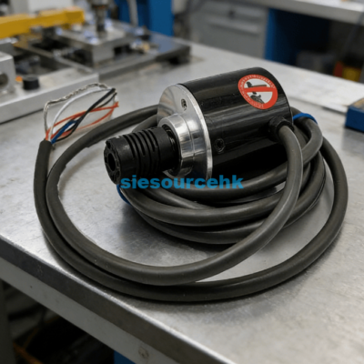
Choosing the correct wiring method is only half the battle; you must also select the right hardware interface. Keyence sensors typically come in three physical connection styles: Pre-leaded, M8 Connector, or M12 Connector.
Pre-leaded vs. Connectorized
Pre-leaded sensors have the cable integrated directly into the housing. These are cost-effective but harder to replace if the cable is damaged. Connectorized versions (M8/M12) allow for “plug-and-play” replacement, significantly reducing downtime in high-speed manufacturing environments.
Determining if the FU-97P Fits Your Needs
When dealing with complex environments, specialized fiber optic sensors like the Keyence FU-97P are preferred. This specific model is a thrubeat type fiber unit known for its ruggedness and long-distance capabilities. If your application involves tight spaces or harsh conditions where a standard photoeye might fail, the FU-97P provides the necessary flexibility.
To ensure you are selecting the correct model for your specific PLC logic, you should verify the output type of the amplifier unit used with the fiber. You can explore detailed technical datasheets and compatibility charts for the Keyence Sensor FU-97P to confirm if it meets your machine’s physical and electrical requirements.
Summary
Wiring a Keyence sensor requires matching the Brown, Blue, and Black wires to your power supply and PLC logic. By identifying whether you need an NPN or PNP setup and adhering to the 12-24V DC standards, you ensure a reliable, high-speed detection system that minimizes electrical interference and hardware damage.
| U-77V | FU-77TZ | FU-40 | FU-15 |
| FU-R67TG | FU-67V | FU-93Z | FU-16Z |
| FU-R67TZ | FU-35FZ | FU-4FZ | CF-SFU-20-B |
| FU-88 | FU-L51Z | FU-66 | FU-12 |
| FU-31 | FU-93Z | FU-35TZ | FU-2412 |
| FU-67TZ | FU-40 | FU-21X | FU-2412 |
| FU-53TZ | FU-77 | FU-52TZ | FU-86H |
FAQ
1. What happens if I reverse the Brown and Blue wires?
Most modern Keyence sensors include reverse polarity protection. However, if the sensor lacks this feature, reversing the power leads can instantly destroy the internal transistors. Always double-check your connections with a multimeter before applying power.
2. Can I use a Keyence sensor with an AC power supply?
Generally, no. Most Keyence industrial sensors are designed for DC voltage (12-24V). Connecting a DC sensor directly to an AC line (like 110V or 220V) will cause an immediate catastrophic failure and poses a significant safety risk.
3. How do I change a sensor from Light-ON to Dark-ON?
This is usually handled by the amplifier unit (like the FS-N series) rather than the physical wiring. Most amplifiers have a toggle switch or a software setting to change the output logic. In some 4-wire sensors, you simply switch your connection from the black wire to the white wire.
4. Why is my sensor outputting a signal even when nothing is there?
This could be due to electrical noise or a “floating” input. Ensure your Blue wire (0V) is properly grounded to the system common. If the issue persists, check if the sensor’s sensitivity is set too high, causing it to detect background objects.
Reference Sources
Keyence Corporation: Sensor Wiring and Connection Basics.
International Electrotechnical Commission (IEC): IEC 60947-5-2 Standard for Proximity Switches.