



Blog
Siemens 3RH2924-1GP11 Specs: 24V DC PLC Coupling Link Guide

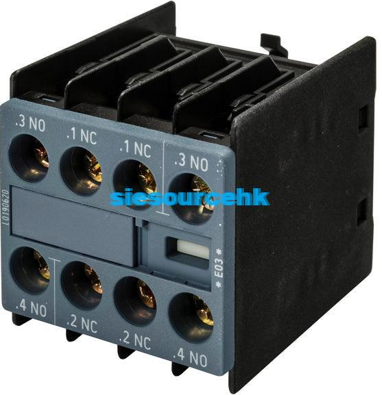
The Siemens 3RH2924-1GP11 is a SIRIUS coupling link designed for PLC control of Siemens 3RT2.2 power contactors. It mounts directly onto the contactor coil terminals and operates with a 24V DC control signal, supporting an operating range of 17–30V DC. The module includes a yellow LED switching indicator and an integrated varistor for suppressing coil switching overvoltages. Its main selection requirements are contactor size S0, screw-terminal construction, and compatibility with the specified 3RT2.2 contactor configuration.
Siemens 3RH2924-1GP11 Technical Specifications
The 3RH2924-1GP11 is an interface accessory between a PLC output and a compatible contactor coil. Rather than replacing the contactor, it provides a dedicated control connection and switching indication.
| Specification | Details |
|---|---|
| Manufacturer | Siemens |
| Product family | SIRIUS 3RH29 |
| Model number | 3RH2924-1GP11 |
| Product type | PLC coupling link |
| Compatible contactor size | S0 |
| Specified contactor application | 3RT2.2 |
| Mounting method | Direct mounting on coil terminals |
| Control supply voltage | 24V DC |
| Operating voltage range | 17–30V DC |
| Power consumption | 0.5 W at rated supply voltage |
| Rated current consumption | 20 mA |
| Release voltage | At least 4 V DC |
| Switching status indication | Yellow LED |
| Surge suppression | Integrated varistor |
| Rated insulation voltage | 300 V |
| Front protection rating | IP20 |
| Operating temperature | -25°C to +60°C |
| Storage temperature | -40°C to +80°C |
| Connection type | Screw terminals |
Source: Siemens SIRIUS IC 10 catalogue, including the official technical and selection documentation. Specifications should be checked against the applicable product revision before installation.
How Does the 3RH2924-1GP11 Work with a PLC?
In a conventional contactor control circuit, a PLC output must operate the contactor coil through an appropriate electrical interface. The 3RH2924-1GP11 is designed to simplify this connection for compatible Siemens 3RT2.2 contactors.
The coupling link receives a 24V DC control signal and provides the interface needed to operate the contactor coil. When the control signal reaches the required operating conditions, the contactor can change its switching state.
This arrangement is particularly useful in automated control cabinets where PLC outputs manage pumps, fans, conveyors, and other motor-driven equipment.
The basic control sequence is:
- The PLC generates a 24V DC switching command.
- The coupling link receives the control signal.
- The interface operates the connected contactor coil under the specified conditions.
- The contactor changes its main contact state to control the connected load.
- The yellow LED provides a visual indication of the coupling link’s switching state.
The coupling link is not a PLC communication module or an independent relay controller. Its function is specifically related to controlling a compatible contactor through its coil connection.
Why Are the LED and Integrated Varistor Important?
Yellow LED switching indication
The integrated yellow LED provides a local visual indication of the coupling link’s switching state. During commissioning or troubleshooting, this can help technicians distinguish between an absent control command and a downstream contactor problem.
However, an illuminated LED alone does not prove that the contactor’s main contacts have closed correctly. Mechanical condition, coil operation, wiring, and load-side electrical conditions must still be checked separately.
Varistor surge suppression
When a DC contactor coil is de-energized, the collapsing magnetic field can generate a voltage transient. The integrated varistor helps suppress this switching overvoltage.
This is important in PLC-controlled installations because electrical transients can interfere with nearby control electronics. The varistor helps limit the coil-related disturbance, although the complete control cabinet may still require appropriate EMC and wiring practices.
3RH2924-1GP11 Compatibility and Installation Requirements
One important detail is that the 3RH2924-1GP11 is not a universal coupling link for every Siemens contactor. Siemens specifies this model for direct mounting on the coil terminals of size S0 contactors, particularly the 3RT2.2 configuration with screw terminals.
Before selecting it, engineers should check the following:
- Contactor size: Confirm that the existing contactor is size S0.
- Contactor series: Verify the specified 3RT2.2 application.
- Terminal construction: Confirm that the contactor uses screw terminals.
- Control voltage: Ensure that the PLC control supply is within 17–30V DC.
- Coil connection: Check the B1/B2 coil terminal arrangement and the manufacturer’s wiring instructions.
For a related Siemens motor switching component, see the Siemens 3RT6015-1AN21 power contactor. It belongs to the broader SIRIUS contactor portfolio, but its suitability with this coupling link must be verified against the exact contactor size and terminal configuration. It should not automatically be treated as a compatible pairing.
3RH2924-1GP11 vs 3RH2914-1GP11: What Is the Difference?
These two Siemens coupling links both support 24V DC PLC control, but their mounting arrangements and intended contactor applications differ.
| Comparison | 3RH2924-1GP11 | 3RH2914-1GP11 |
|---|---|---|
| Product function | PLC coupling link | PLC coupling link |
| Control voltage | 24V DC | 24V DC |
| Operating range | 17–30V DC | 17–30V DC |
| Mounting method | Direct mounting on coil terminals | Front mounting |
| Contactor size | S0 | S00 to S3, subject to the specified contactor series |
| Terminal arrangement | Screw-terminal contactor application | Front-mounted interface |
The main difference is the physical installation method. The 3RH2924-1GP11 connects directly at the coil terminals, whereas the 3RH2914-1GP11 uses front mounting. These mounting differences matter when retrofitting an existing control panel or selecting accessories for a new contactor assembly.
Do not choose between them based on control voltage alone. Verify the contactor model, mounting space, terminal design, and manufacturer’s selection information.
What Should Buyers Check Before Ordering?
For replacement and maintenance projects, the complete Siemens order number should be checked before purchasing. A visually similar coupling link may have a different mounting arrangement or intended contactor application.
Before requesting a quotation, prepare:
- The complete part number: 3RH2924-1GP11.
- The connected Siemens contactor model.
- The required quantity.
- The control supply voltage.
- The existing terminal and mounting configuration.
- The required product condition and delivery destination.
For additional Siemens automation and control components, visit the Siesource industrial automation product catalogue. If you need this exact coupling link, provide the complete model number and connected contactor reference through the Siesource contact page so the required configuration can be reviewed before ordering.
Frequently Asked Questions
What is Siemens 3RH2924-1GP11 used for?
It is a 24V DC PLC coupling link designed for direct mounting on the coil terminals of compatible Siemens 3RT2.2 size S0 contactors. It provides a control interface, LED indication, and varistor suppression.
What is the operating voltage range of 3RH2924-1GP11?
Its rated control supply is 24V DC, with a specified operating range of 17–30V DC.
Does the 3RH2924-1GP11 have surge protection?
Yes. It includes an integrated varistor to suppress switching overvoltages generated by the contactor coil.
Can the 3RH2924-1GP11 be used with every Siemens 3RT contactor?
No. This model is specified for direct coil-terminal mounting on size S0 3RT2.2 contactors with screw terminals. Other contactor sizes and configurations require separate compatibility verification.
Conclusion
The Siemens 3RH2924-1GP11 is a specialized PLC coupling link for 24V DC control of compatible SIRIUS 3RT2.2 contactors. Its 17–30V DC operating range, yellow LED indication, integrated varistor, and direct coil-terminal mounting make it a practical interface for specific S0 contactor installations. The most important selection step is confirming the exact contactor model and screw-terminal configuration rather than assuming that the accessory fits every Siemens contactor.