Blog
How to Identify the Right Keyence Cable for Your Sensor ?
Identifying the right keyence cable requires a precise match between your sensor series and the required signal transmission medium. You must first determine if your system utilizes photoelectric, fiber optic, or proximity sensors. The most reliable way to ensure compatibility is to cross-reference the sensor head part number with the specific connector pin configuration. This prevents electrical shorts and ensures high-speed data flow in demanding automation environments. Selecting the wrong cable can lead to signal attenuation or permanent hardware damage.
Industrial automation systems rely on two primary cable categories: power-signal connector cables and fiber optic transmission lines. If you are using a fiber amplifier like the FS-N series, you will specifically need a keyence fiber optic cable to connect the sensing head. For standard photoelectric sensors, a physical wire connection via M8 or M12 connectors is common. Checking the number of pins, usually 3-pin or 4-pin, is critical for power and output synchronization. Modern digital sensors often require specialized shielding to resist electromagnetic interference (EMI) on the factory floor.
The physical environment of your installation also dictates the necessary cable specifications. Cables in robotic arms must withstand millions of bending cycles without internal wire fatigue. High-flex or “tough-flex” cables are designed with specialized internal structures to maintain conductivity under constant movement. Conversely, stationary sensors may only require standard PVC-jacketed lines for cost-effective implementation. This article provides a comprehensive roadmap for identifying the exact cable requirements for your Keyence sensing hardware.
Factors to Consider When Selecting Keyence Connector Cables
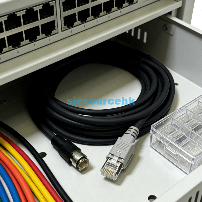
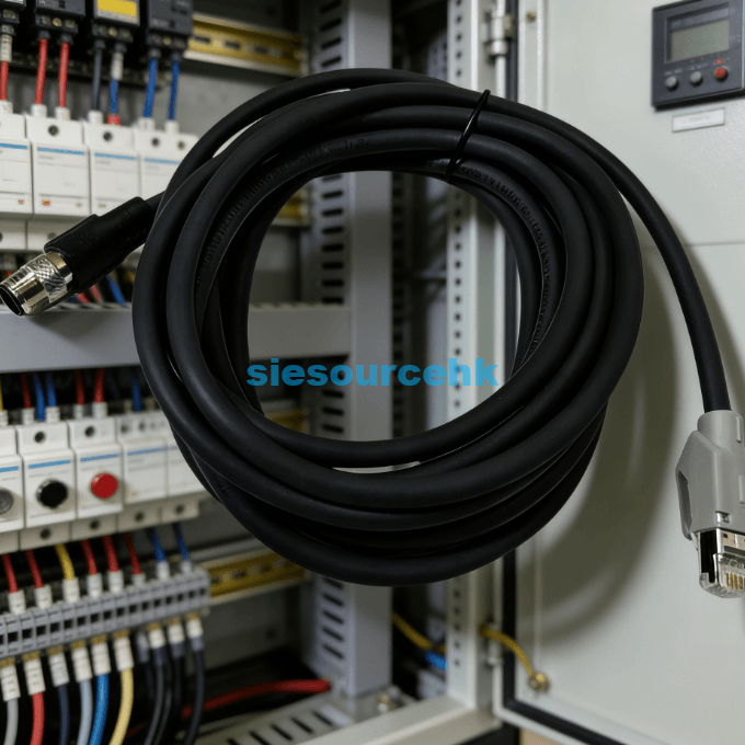
Selecting keyence connector cables involves evaluating the physical connection type and the electrical requirements of the application. Most Keyence sensors utilize standardized M8 or M12 circular connectors, but the internal wiring varies by model. You must verify if your sensor outputs a PNP or NPN signal, as this affects the wire color coding and logic. Using a cable like the OP-26751 provides a standard 4-pin M12 connection suitable for a wide range of digital outputs. Standardizing your cable lengths across the facility can also simplify maintenance and reduce spare part inventory costs.
Understanding Connector Types and Pin Configurations
The first step in identification is determining the physical size of the connector. M8 connectors are typically used for compact sensors with limited space, while M12 connectors are standard for larger, more robust units. You must count the number of female or male pins on the sensor body before ordering. A 4-pin configuration usually supports power, ground, and two separate outputs or a control input.
Key technical details for connector selection include:
- Connector Head Angle: Choose between straight and L-shaped connectors for tight installations.
- Locking Mechanism: Ensure the screw-on or snap-on lock matches the sensor’s thread type.
- Cable Length: Standard lengths like 2m, 5m, and 10m are available to minimize excess slack.
- Jacket Material: PUR (Polyurethane) is better for oil resistance, while PVC is standard for dry areas.
Electrical Integrity and Shielding Requirements
Electrical noise is a significant factor in industrial signal failures. High-precision sensors often require shielded keyence connector cables to prevent false triggers caused by nearby motors. Shielded cables utilize a metal braid or foil to drain static and EMI safely to the ground. This is particularly important for analog signals where a small voltage drop can lead to measurement errors. Always check if your sensor datasheet specifies “shielded” or “twisted pair” for optimal performance.
Understanding Keyence Fiber Optic Cable Varieties
When working with fiber optic sensors, the selection process focuses on the keyence fiber optic cable rather than electrical wires. These cables do not carry electricity; instead, they transmit light between the amplifier and the sensing head. You must choose between plastic and glass fibers depending on the required detection distance and temperature. Plastic fiber cables are more flexible and cost-effective for general-purpose sensing at room temperature. However, glass fibers are necessary for environments exceeding 70 degrees Celsius.
Performance Tiers of Plastic and Glass Fibers
The core material of a keyence fiber cable determines its light transmission efficiency. Plastic fibers, like the FU series, are easy to cut to a custom length using a specialized cutter. Glass fiber cables are typically pre-assembled and cannot be shortened manually without specialized equipment. Glass is superior for long-range detection because it has lower light attenuation over several meters. Choosing the wrong core material can lead to “low light” errors on your amplifier display.
Thrubeam vs. Reflective Fiber Architectures
A keyence fiber cable is configured as either a thrubeam or a reflective system. Thrubeam systems require two separate cables: one for the emitter and one for the receiver. Reflective fiber heads combine both functions into a single unit for space-saving installation. Reflective systems are easier to mount but generally have a shorter sensing range than thrubeam setups. You must match the fiber head design to your target object’s size and color.
Technical Specifications of Keyence Fiber Optic Cables
The durability of a keyence fiber optic cable is measured by its minimum bending radius and environmental ratings. If a fiber cable is bent too sharply, the internal light path can be disrupted or the core can fracture. Tough-flex fiber cables can often handle a bending radius as small as 2mm to 4mm. This makes them ideal for installation inside compact machine enclosures or along complex routing paths. Standard cables may require a larger radius of 15mm to 25mm to avoid damage.
Evaluating Environmental Resistance and Durability
Industrial sensors are often exposed to harsh chemicals, oils, and high temperatures. A keyence fiber optic cable must be rated to withstand these specific conditions to avoid brittleness. Stainless steel jacketing provides the highest level of mechanical protection against sharp metal shavings. For chemical washdown areas, fluororesin-coated fibers are used to prevent corrosive erosion. Data shows that environmental degradation is responsible for nearly 40% of fiber sensor failures in the food processing industry.
Sensing Distance and Precision Targets
The diameter of the fiber core impacts the sensing distance and the minimum detectable object size. Fine-core keyence fiber optic cables are designed for detecting extremely small parts like electronic components. Larger core diameters allow for longer sensing ranges but may struggle with precision alignment. You should consult the amplifier’s “long-range” or “high-speed” settings to match the selected cable’s capabilities. Correct calibration between the cable and the FS-N amplifier ensures a stable detection threshold even in dusty environments.
Judging Suitability for Your Automation System
Selecting the correct hardware involves balancing performance needs with physical installation constraints. A professional keyence cable should offer a secure, vibration-resistant connection to ensure continuous uptime. The choice of cable often determines the maximum speed at which your sensor can operate without losing data. When evaluating your options, consider the frequency of movement the cable will undergo. You can browse specific technical parameters for various sensors and their compatible lines at the Siesourcehk Photoelectric & Fiber Optic category to see how different heads pair with specific cabling.
Furthermore, always verify the specific model numbers for accessories like connector converters or extension leads. A standard keyence cable like the OP-26751 is a versatile choice for many M12-compatible sensors. Checking the length and jacket type before procurement ensures that the cable fits your machine layout without unnecessary modifications. Professional vendors provide detailed datasheets that outline the voltage ratings and temperature tolerances for every cable series. Selecting a part based on these verifiable metrics is the best way to prevent project delays.
Summary
To identify the right keyence cable, you must match the sensor’s pin configuration for electrical lines or the core material for a keyence fiber optic cable. Prioritizing factors like bending radius, jacket material, and connector size ensures long-term reliability. By cross-referencing your sensor head model with the manufacturer’s cable guide, you can eliminate compatibility errors and optimize your automation system’s signal performance.
| OP-88837(IV) | OP-88837 | OP-87458 | OP-87441 |
| OP-87910 | OP-88812 | OP-87445 | OP-87404 |
| OP-88837(10m) | OP-88811 | OP-87444 | OP-87632 |
| OP-88837 | OP-87226 | OP-87404 | OP-73864 |
| OP-88836 | OP-88680 | OP-87232 | OP-88644 |
| OP-88812 (10M) | OP-88650 | OP-87231 | OP-88640 |
| OP-88649 | OP-88642 | OP-84396 | OP-88837 |
| OP-87905 | OP-76874 | OP-51612 | OP-88656 |
| OP-87458 | OP-42339 | OP-26751 | OP-87890 |
| OP-87451 | OP-87900 | OP-88807 | OP-87890 |
| OP-87440 | OP-87587 | OP-88684 | OP-87904 |
| OP-88697 | OP-88301 | OP-87527 | OP-66843 |
| OP-88679 | OP-87359 | OP-87458 | OP-51580 |
| OP-87504 | OP-87055 | OP-87910 | OP-87906 |
| OP-87259 | OP-87899 | OP-87900 | OP-87910 |
| OP-87909 | OP-87056 | OP-88002 | OP-87225 |
| OP-87277 | OP-73865 | OP-87231 | OP-87361 |
| OP-87636 | OP-87231 | OP-87354 | OP-87355 |
| OP-87360 | OP-88696 | OP-87360 | OP-87890 |
| OP-88696 | OP-88678 | OP-87226 | OP-87771 |
| OP-88678 | OP-88471 | OP-88027 | OP-87641 |
| OP-88471 | OP-88542 | OP-87274 | OP-85502 |
| OP-88542 | OP-87450 | OP-88696 | OP-87904 |
| OP-87461 | OP-88679 | OP-88841 | – |
FAQ
1. Can I use a standard M12 cable with a Keyence sensor?
In many cases, yes, provided the pin configuration and voltage rating match the sensor’s requirements. However, using a genuine keyence cable ensures the correct shielding and connector fit for industrial environments. Always check the sensor datasheet to confirm the wire color coding is compatible with your PLC input.
2. How do I know if I need a plastic or glass keyence fiber optic cable?
Choose plastic fibers for general-purpose use and tight bends where temperatures stay below 70°C. Glass keyence fiber optic cables are necessary for high-heat areas or when you require extremely long-distance sensing. Glass fibers are also more resistant to certain chemical solvents that might damage plastic cores.
3. What is the benefit of a “tough-flex” keyence fiber cable?
Tough-flex fibers are specifically engineered to resist breakage during repeated bending in robotic applications. A tough-flex keyence fiber cable can maintain a small bending radius without losing light intensity. This allows for more compact machinery designs and significantly longer service life in dynamic parts of the line.
4. What does the OP-26751 cable connect to?
The OP-26751 is a common connector cable used with various Keyence sensors that feature an M12 4-pin interface. It is often used with photoelectric sensors and light curtains to provide power and transmit digital signals. Its robust design makes it suitable for standard factory floor conditions.
5. Why is my fiber sensor showing a “low light” error?
A “low light” error often indicates a mismatch between the keyence fiber cable and the amplifier, or a dirty fiber tip. It can also be caused by exceeding the maximum bending radius, which prevents light from reaching the receiver. Ensure the fiber is cut cleanly and correctly seated in the amplifier’s insertion port.
Reference Sources
Keyence Corporation – Official Product Technical Data and Selection Guide
International Electrotechnical Commission (IEC) – Standard 61076-2-101 for M12 Connectors
IEEE – Industrial Communication and Ethernet Standards for Sensors