


Blog
Integrating SINAMICS S120 Power Connectors: Expert Guide

The Siemens SINAMICS S120 is the gold standard for high-performance modular drive systems in industrial automation. However, the integrity of an S120 system depends heavily on how the power connectors are integrated. Poor integration leads to EMI (Electromagnetic Interference), thermal failure, or costly downtime.
For project managers and lead engineers, understanding the SINAMICS S120 Power Connector is not just about choosing a plug. It is about understanding the electrical and mechanical synergy between the Power Module, Motor Module, and the Control Unit. This guide explores the technical logic behind S120 power integration, focusing on hardware compatibility and commercial selection criteria.
The Modular Architecture of S120 Integration
The SINAMICS S120 system is inherently modular. Integration begins with identifying the hardware format: Booksize, Compact, or Chassis. Each format utilizes different power connector interfaces to manage current density and space constraints.
In Booksize modules, power integration often relies on the DC link busbars. These connectors bridge the Power Module (PM) to multiple Motor Modules (MM). This design minimizes wiring complexity. For larger Chassis units, integration shifts toward heavy-duty terminal connections. These must handle significantly higher thermal loads and mechanical stresses.
DC Link and 24V DC Busbar Integration
The DC link is the backbone of the S120 system. Integrating the power connector here requires precise alignment of the reinforced busbar adapters. Engineers must ensure that the “Electronic Power” (24V DC) is integrated alongside the high-voltage DC link. This dual-layer integration ensures that the control electronics remain active even if the main power is disconnected.
| Component Type | Connection Method | Integration Focus |
|---|---|---|
| Booksize (Internal) | Busbar / Slide-in | Current sharing & heat dissipation |
| Booksize (External) | MOTION-CONNECT Plug | Speed of replacement & vibration resistance |
| Chassis Units | Bolted Terminal | Torque precision & contact resistance |
| Combi Modules | Integrated Terminals | Compact footprint for CNC applications |
High-Performance Cabling and Connector Synergy
Integration is incomplete without discussing the cable-to-connector interface. Siemens utilizes the MOTION-CONNECT system (500, 700, and 800 series) to ensure seamless integration with S120 power connectors. The 6FX series cables are designed with pre-assembled connectors. These offer “Turn-and-Lock” mechanisms that prevent accidental disconnection in high-vibration environments like robotic arms or CNC spindles.
EMC-Compliant Integration
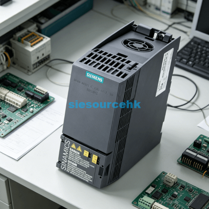
Electromagnetic Compatibility (EMC) is a non-negotiable factor in drive technology. The SINAMICS S120 power connector acts as the primary grounding point for cable shields. Effective integration requires the shield to be connected over a large surface area using shield plates or EMC clips.
This prevents high-frequency switching noise from the IGBTs from interfering with nearby sensor signals or DRIVE-CLiQ communication. From a manufacturing perspective, skipping proper EMC integration is the leading cause of “ghost” faults in S120 systems.
Critical Engineering Factors for Power Connector Selection
When sourcing SINAMICS S120 components from specialized distributors like Siesource Drive Technology, engineers must evaluate specific technical parameters.
1. Current Rating and Derating Factors
Integration must account for ambient temperature and altitude. If the S120 cabinet operates in an environment above 40°C, the power connector’s current capacity must be derated. Using an undersized connector leads to localized overheating and carbonization of the contact housing.
2. Degree of Protection (IP Rating)
For wash-down environments in food and beverage or harsh chemical processing, the connector integration must meet IP65 or IP67 standards. Standard S120 connectors are often IP20; therefore, external interface boxes or specialized protective housings are required for field-level integration.
3. Vibration and Mechanical Stress
In dynamic applications, such as gantry systems, the power connector experiences constant mechanical stress. Integration strategies should include strain relief brackets. This ensures that the weight of the MOTION-CONNECT cable does not put leverage on the S120 Motor Module’s internal PCB.
Integration Logic in Multi-Axis Systems
In complex OEM machinery, multiple S120 Motor Modules are often daisy-chained. This creates a “Drive Line-up.” The integration logic here involves the Line Connection Module (LCM). The power connector at the LCM must be rated for the total cumulative current of all downstream axes.
System designers must calculate the “Total Peak Current” versus the “Continuous Rated Current.” The connector choice at the head of the DC link is the most critical single point of failure in the entire drive train.
Procurement and Lifecycle Considerations
For B2B buyers and MRO (Maintenance, Repair, and Operations) managers, the commercial aspect of S120 power connectors is about long-term availability and certification.
- Genuine vs. Third-Party Connectors: While third-party connectors might offer lower upfront costs, they rarely match the tolerances of Siemens MOTION-CONNECT standards. Incompatible pin tolerances can lead to “micro-arcing,” which eventually destroys the pins on the expensive S120 Motor Module side.
- Global Compliance (UL/CE/CSA): For machines intended for export, the power connector integration must comply with regional standards. SINAMICS S120 components are generally UL/CSA listed. However, the integration method (wiring methods, conduit use) must also meet NFPA 79 or local electrical codes to pass factory inspection.
Summary
Successful integration of the SINAMICS S120 power connector requires a balance between electrical precision and mechanical durability. By focusing on EMC shielding, thermal derating, and the use of genuine MOTION-CONNECT cabling, engineers can ensure system longevity. Strategic sourcing from verified partners like Siesource remains critical for maintaining OEM performance standards in high-demand industrial environments.
| 6SL3130-6AE21-0AB1 | 6SL3120-1TE23-0AA4 | 6SL3120-1TE23-0AA4 | 6SL3130-7TE31-2AA3 |
| 6SL3060-4AB00-0AA0 | 6SL3210-1PE14-3AL1 | 6SL3210-1PE27-5AL0 | 6SL3210-1PE26-0AL0 |
| 6SL3120-1TE23-0AA4 | 6SL3120-1TE23-0AD0 | 6SL3130-7TE21-6AA4 | 6SL3120-1TE21-8AD0 |
| 6SL3100-0BE21-6AB0 | 6SL3040-1MA01-0AA0 | 6SL3000-0BE23-6DA1 | 6SL3120-1TE13-0SP0 |
| 6SL3130-7TE25-5AA3 | 6SL3120-1TE23-0AA4 | 6SL3350-6TK00-0EA0 | 6SL3351-1AE32-1AA2 |
FAQ
1. Can I reuse S120 power connectors after a module failure?
It is not recommended. If a Motor Module fails due to a short circuit, the power connector has likely been subjected to thermal stress or ionization. For mission-critical systems, replacing both the module and the connector is the best practice to prevent secondary failures.
2. What is the difference between the 6FX5008 and 6FX8008 cable connectors?
The 6FX8008 series is designed for continuous motion (drag chains), meaning the connector integration includes enhanced strain relief and more robust internal crimping to handle constant bending cycles.
3. How do I ensure a secure ground connection at the power connector?
Use the integrated shield plate provided with the S120 module. The cable shield should be stripped and clamped directly to the plate using a metallic U-clamp. Avoid using “pigtail” ground wires, as they act as antennas for high-frequency noise.
4. Does the S120 Power Connector support Safety Integrated functions?
The power connector handles the 3-phase AC output or DC link power. While it doesn’t carry the “Safe Torque Off” (STO) logic signals, the physical integrity of the power connection is vital for the “Safe Brake Control” (SBC) function often integrated into the power cable.
5. What is the maximum cable length supported by S120 power connectors?
This depends on the Line Module type and whether an output reactor is used. Generally, for unshielded cables, it’s 50m-100m, but with high-quality shielded MOTION-CONNECT cables and proper connector integration, longer runs are possible without violating EMC limits.
Reference Sources
Siemens Industry Online Support: SINAMICS S120 Manual
International Electrotechnical Commission: IEC 61800-3
Underwriters Laboratories: UL 508C Safety Standard
Siesource Drive Technology: SINAMICS S120 Components