
Blog
Industrial Power Device TD180N16KOF: 1600V High-Voltage Working Condition Withstand Design and Heat Dissipation Advantages

Infineon Technologies IGBT Module TD180N16KOF Thermal Guide
Meta Description: An in-depth engineering analysis of the 1600V withstand capacity and advanced heat dissipation design of the Infineon Technologies IGBT Module TD180N16KOF.
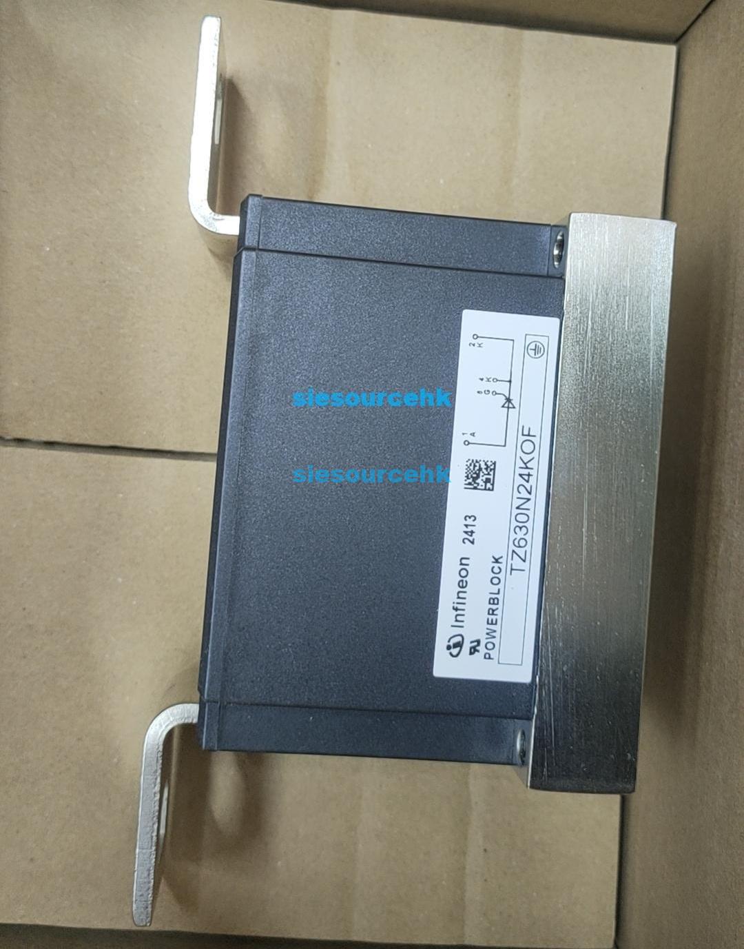
Managing high-voltage and high-current electrical transients in modern industrial manufacturing requires robust power semiconductors. Among the standard components utilized in industrial power converters, motor controllers, and AC soft starters, the Infineon Technologies IGBT Module TD180N16KOF represents a critical building block. Although often designated or listed by electrical distributors under the general category of “IGBT Modules,” this device is technically a high-performance Thyristor-Diode (SCR-Diode) phase control module.
Understanding this precise silicon topology is vital for hardware engineers and manufacturing consultants. Integrating this module into rough-service industrial equipment requires solid electrical withstand margins and optimal cooling pathways. This deep-dive study examines the electrical limits, thermal contact technologies, and engineering safety boundaries of this power block.
Industrial Power Device TD180N16KOF: 1600V High-Voltage Working Condition Withstand Design and Heat Dissipation Advantages
Why Choose the TD180N16KOF for High-Voltage Applications?
The performance of any power electronic system under heavy industrial working conditions depends directly on its voltage de-rating factor. Operating directly from three-phase industrial mains (typically 400V to 480V AC) subjects semiconductors to massive back-EMF, lightning-induced line surges, and harmonic voltage peaks. The Infineon Technologies IGBT Module TD180N16KOF addresses this threat with a repetitive peak reverse and off-state voltage ( and ) rated at 1600V.
This 1600V withstand limit provides a critical safety buffer of more than three times the nominal grid voltage. In industrial systems, this margin is crucial for maintaining insulation integrity and preventing catastrophic avalanche breakdown in the silicon junctions. Standard transients are absorbed within the safe operating area of the thyristor, preventing localized hot spots that lead to gate-terminal punch-through.
Furthermore, the module boasts a maximum surge on-state current () capacity of 5400A for a standard 10ms half-sine pulse at maximum junction temperature. This high transient surge capability allows the system’s upstream fuses or rapid circuit breakers to isolate faults prior to solid-state device deterioration, reducing unscheduled repair downtime in high-power manufacturing environments.
Advanced Heat Dissipation Advantages of Pressure Contact Modules
When running at its rated average on-state current () of 180A, power dissipation within the silicon switches generates intense thermal loads. To sustain structural integrity, heat must be evacuated from the silicon junction to the external heat exchanger with minimal thermal impedance. The physical construction of the Infineon Technologies IGBT Module TD180N16KOF uses several key design strategies to minimize thermal resistance:
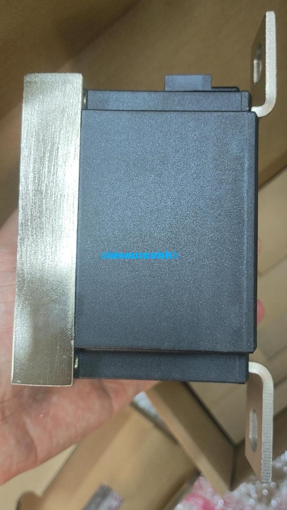
- Pressure Contact Technology: Unlike conventional solder-bond modules which rely on large solder layers that are prone to voids and thermal stress fatigue, this module holds the silicon dies in place under high mechanical pressure. This prevents micro-fracturing under rapid thermal cycling courses (e.g., in cyclic soft-starter profiles), improving service lifetimes.
- Direct Copper Bonding (DBC) Baseplate: The inner isolation plate uses high-purity ceramic material bonded between thick copper layers. This provides an insulation voltage rating of 3600V RMS (for 1 minute) while maintaining a low thermal resistance from junction to case () of only 0.164 K/W for the thyristor element.
- Optimized Case-to-Heatsink Interface: The module utilizes a flat copper interface plate, resulting in a low case-to-heatsink contact thermal resistance () of 0.05 K/W when proper thermal joint compound (such as high-conductivity silicone grease) is applied.
By ensuring a direct, pressure-clamped thermal path, local heat spikes are distributed evenly across the baseplate, lowering total thermal stress.
Industrial Power Device TD180N16KOF: 1600V High-Voltage Working Condition Withstand Design and Heat Dissipation Advantages
High-Impact Application Scenarios in Industrial Automation
Due to its robust phase-control SCR integration, this device excels in applications requiring continuous, precise AC voltage adjustment or solid-state input rectification. Some of the most common system environments where this electrical block is deployed include:
- Industrial AC Soft Starters: By controlling the conduction phase angle of the SCR, the startup surge current of three-phase induction motor windings can be limited smoothly. Heavy inertia loads in conveyor belts, industrial fans, and crushers rely heavily on these starters.
- Input Rectifier Bridges for Variable Frequency Drives (VFDs): High-power motor control in water treatment stations, paper mills, and mining hoists requires raw DC power buffers. The highly robust 1600V diode-thyristor block acts as a dependable front-end mains rectifier.
- Controlled Heating Control Systems: For glass manufacturing, plastics extrusion, and induction furnace systems, high-power heating elements demand steady, pulse-modulated power flows. SCR phase control easily manages several hundred kilowatts of heating energy with zero mechanical contact wear.
- Uninterruptible Power Supplies (UPS): In heavy medical or server facilities, high-capacity static bypass switches utilize these modules to switch grid-to-inverter backups instantly with minimal switching loss.
How to Calculate the Thermal Budget for the Infineon Technologies IGBT Module TD180N16KOF?
Engineers designing industrial power panels must run systematic thermal budget audits to keep the worst-case junction temperature () below the absolute physical maximum of 125°C. Calculating the maximum permitted heatsink thermal resistance () is performed using a basic thermal Ohm’s law model:
Where:
- = Maximum operating junction temperature (typically budgeted at 115°C for a conservative 10°C environmental margin).
- = Ambient ambient temperature inside the power cabinet (typically up to 50°C under industrial conditions).
- = Total power dissipated inside the module (product of RMS operating current and forward voltage drop, roughly ).
- = Junction-to-case thermal resistance (0.164 K/W).
- = Case-to-heatsink contact resistance (0.05 K/W).
If the RMS current through the SCR-diode is 150A, and the worst-case forward voltage drop is 1.25V, the continuous power dissipation () is approximately 187.5 Watts. Rearranging the formula to find the maximum allowed thermal resistance of the heatsink:
Therefore, the designer must select an active, fan-cooled extruded aluminum heatsink with a thermal resistance rating of 0.132 K/W or less to guarantee the silicon junctions do not experience thermal runaway.
Parametric Breakdown of High-Voltage Withstand Performance
For rapid comparison against standard thyristor blocks or dual IGBT structures, the core industrial parameters of this module are summarized below:
| Technical Metric / Spec Name | Design Parameter Value | Structural & Safety Significance in Design |
|---|---|---|
| Silicon Technology Type | Phase-Control Thyristor / Diode | Reliable phase-angle AC voltage control and rugged rectification |
| Repetitive Peak Voltages () | 1600 Volts | Protects against grid overvoltage transients and EMF feedback |
| Average On-State Current () | 180 Amps () | Continuous capacity for heavy-duty industrial electric drives |
| Max Surge Pulse Current () | 5400 Amps () | Ensures fuse protection action prior to internal silicon failure |
| Critical Rate of Rise () | 1000 V/µs | Protects against high-frequency switching noise triggering |
| Thermal Resistance () | 0.164 K/W (Thyristor) | Facilitates heat flow out of the silicon junction |
| Insulation Isolation Voltage () | 3600V RMS () | Protects operators and sensitive chassis electronic circuits |
Technical Suitability Evaluation for Industrial Integration
When designing high-power electrical setups or selecting drop-in replacements for failed devices, electrical designers must ensure physical dimensions and terminal terminals match the original footprint exactly. Sourcing certified power semiconductors through authorized, traceable procurement routes is critical for avoiding counterfeit parts that can cause high-energy failures.
For OEM development teams and procurement professionals assessing parts for next-generation platforms, evaluating verified product profiles like the SIESOURCE TD180N16KOF Platform Page serves as an excellent starting point. Referencing such comprehensive sourcing nodes during design phases enables procurement officers to verify physical package configurations, double-check mechanical bolt-torque limits, and confirm steady stock availability for volume industrial manufacturing pipelines. This proactive alignment minimizes scaling bottlenecks and ensures standard compliance across global distribution chains.
FAQ
A standard IGBT (Insulated Gate Bipolar Transistor) module uses high-speed voltage-controlled transistors designed for high-frequency switching (typically 2kHz to 50kHz) such as PWM inverters. In contrast, the TD180N16KOF is a phase-controlled Thyristor-Diode (SCR-Diode) module. It switches at grid frequencies (50Hz/60Hz) using current-pulsed gates. It excels in heavy phase-angle control, rectifier inputs, and soft-starters due to its massive surge current capacity, which is significantly higher than that of comparable IGBTs.
Soldered bonds are prone to thermal cycling wear. As the module heats and cools, the mismatch in thermal expansion coefficients between copper, ceramic, and silicon strains the solder layers, resulting in voids, micro-cracks, and localized hotspots. Pressure contact technology replaces internal solder joints with mechanical springs that apply constant pressure. This maintains uniform electrical and thermal contact, dramatically increasing thermal-cycling lifetime and safeguarding against vibration failures.
In Infineon’s industrial power semiconductor coding, ’16’ designates a repetitive peak off-state/reverse voltage rating of 1600V (multiply the number by 100). ‘K’ denotes a package style with mechanical pressure contact technology. ‘O’ indicates a module housing with optimized gate lead routes, and ‘F’ represents a standard fast or controlled gate recovery process tailored for classic phase-control configurations.
No. With an average on-state current rating of 180A, even small currents like 20A generate 25-30W of heat due to the device’s inherent forward voltage drop. Without a heatsink, the module’s small physical thermal mass would overheat in seconds. A heatsink (either forced-air or natural convection) is always mandatory to maintain case temperature below safe operational thresholds.
Reference Sources
Infineon Technologies – Technical Information on Thyristor-Diode Modules
- Author: Infineon Technologies AG
- Source: Official Datasheet & Thermal Application Guide (AN2012-01)
- URL: https://www.infineon.com
IEEE Std 1014-2019: Application Guide for Power Semiconductors
- Author: IEEE Power Electronics Society
- Source: IEEE Standards Association Document Pool
- URL: https://ieeexplore.ieee.org
IEC 60747-6: Discrete semiconductor devices – Part 6: Thyristors
- Author: International Electrotechnical Commission
- Source: IEC Webstore / Safety and Quality Standards
- URL: https://webstore.iec.ch