
Blog
Allen-Bradley 440R Safety Relay: The Ultimate Wiring & Application Guide

1. Electrical Safety Principles & GSR Family Architectures
In modern industrial environments, the integration of dedicated safety control logic is not merely a regulatory mandate—it is a foundational electrical design practice. The Allen-Bradley Guardmaster Safety Relay (GSR) 440R series, developed by Rockwell Automation, represents a highly versatile, modular platform designed to interface with E-stops, safety light curtains, interlocks, and pressure mats. By utilizing specialized dual-channel internal processors and force-guided safety output contacts, these devices ensure that no single component failure can lead to the loss of the safety guard function.
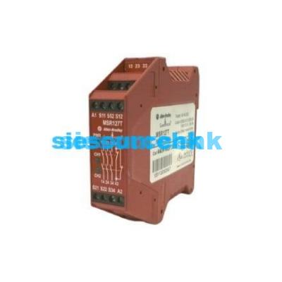
The most prominent models in the GSR lineup are the 440R-D22R2 (DI Dual Input Relay) and the 440R-DIS22 (DIS Dual Input Solid-State output relay). These devices feature specialized diagnostic indicators, rotary function selection switches, and single-wire safety connections for cascading signals across multiple devices.
Understanding the internal architecture of the 440R series is essential for proper machine integration. Unlike standard control relays, a safety relay employs redundant internal pathways. When a demand is placed on the safety system (e.g., pressing an emergency stop button), both internal channels must de-energize. If a single channel welds or fails, the remaining channel safely cuts power, and the relay’s internal monitoring logic blocks subsequent re-start attempts until the fault is diagnosed and corrected.
| Characteristic / Parameter | Rockwell Allen-Bradley 440R-D22R2 Specification |
|---|---|
| Supply Voltage (A1/A2) | 24V DC (+10%, -15%), Class 2 or SELV/PELV power source |
| Power Consumption | 2.5 W typical (excluding external sensor loads) |
| Safety Input Terminals | S12 (Channel 1 Input), S22 (Channel 2 Input) |
| Test Output Pulses | S11 (Channel 1 Source), S21 (Channel 2 Source) |
| Feedback / Reset Loop | S34 (Feedback loop with manual/auto reset options) |
| Safety Relay Contacts | 2 N.O. Force-Guided Contacts (Terminals 13/14, 23/24) |
| Auxiliary Output Contact | 1 N.C. Diagnostic Solid-State / Contact (Terminal 31/32 or 31/32 SSR) |
| Operating Temperature | -5°C to +55°C (23°F to 131°F) |
| Environmental Protection | IP40 (Enclosure), IP20 (Terminal blocks) |
| Performance Level Compliance | ISO 13849-1 Performance Level e (PL e), Category 4 |
2. Comprehensive Terminal Mapping & Wiring Topology
Correct wiring of a GSR safety relay is paramount to achieving the targeted safety category. Terminal configurations are marked on the face of the 440R unit and must be strictly adhered to during cabinet assembly.
2.1 Power and Grounding (A1 and A2)
The safety relay requires a stable 24V DC SELV/PELV supply connected to terminal A1 (+24V) and A2 (0V Ground). To ensure adequate noise immunity and surge protection, the Class 2 power supply must be properly bonded, and a dedicated fuse or circuit breaker must isolate the safety circuit from noisy motor-starter circuits.
2.2 Dual-Channel E-Stop Wiring with Cross-Fault Detection
Cross-fault monitoring is a vital diagnostic feature of Category 4 safety systems. A cross-fault occurs when an insulation breakdown causes a short circuit between the two safety input channels. Standard 24V DC loops may fail to open during a short, keeping the relay energized even if the safety button is pushed.
The 440R safety relay prevents this hazard by generating unique high-frequency test pulses on terminals S11 and S21.
- Channel 1 loop begins at S11, routes through the first Normally Closed (N.C.) contact of the emergency stop switch, and returns to S12.
- Channel 2 loop begins at S21, routes through the second N.C. contact of the emergency stop switch, and returns to S22.
Because the internal logic expects S11 pulses on S12, and S21 pulses on S22, a cross-short between Channel 1 and Channel 2 immediately corrupts the pulse matching. The safety relay detects this corruption within milliseconds, drops its safety outputs, and locks into a fault state.
[24V DC PELV Supply] ---> Fuse ---> A1 (Relay Power) [0V DC PELV Supply] ----------------> A2 (Relay Common) [Safety Relay 440R] +------+ +------+ +------+ +------+ +------+ | S11 | | S12 | | S21 | | S22 | | S34 | +--+---+ +--^---+ +--+---+ +--^---+ +--^---+ | | | | | +---[ E-Stop + +---[ E-Stop + | Contact 1 ] Contact 2 ] | | +------------------[ Monitored Manual Reset ]--------------+ | (Momentary N.O. Pushbutton) v [24V DC] ---> [ K1 Aux N.C. ] ---> [ K2 Aux N.C. ] ---> [ Reset Switch ] ---> S34
3. Designing Reset Loops & External Device Monitoring (EDM)
A failure of downstream output devices (such as welded contacts on a large motor contactor) must block the safety system from resetting. This feedback loop is implemented using External Device Monitoring (EDM).
3.1 Monitored Manual Reset vs. Automatic Reset
The 440R relay’s rotary selector switch defines how the reset terminal S34 is processed:
- Automatic/Manual Reset: In this mode, as soon as the safety inputs (S12/S22) are closed, the relay safety outputs (13/14, 23/24) immediately close. If S34 is closed, it resets without checking for a transition edge.
- Monitored Manual Reset: S34 logic monitors a transition of a momentary Normally Open (N.O.) pushbutton. The reset button must be pressed (closed) and released (opened). This dynamic falling-edge detection ensures that if the reset button is welded shut, or held down with electrical tape, the safety relay will not restart, protecting workers from unexpected machinery startup.
3.2 Feedback Loop Construction (EDM)
To monitor downstream contactors K1 and K2:
- Connect the auxiliary Normally Closed (N.C.) force-guided contacts of contactor K1 and K2 in series.
- Wire this series connection between the 24V supply (or S11) and the Reset Switch, terminating at S34.
- If either K1 or K2 fails to open when the safety relay drops its outputs (i.e., its power contacts weld shut), its auxiliary N.C. contact remains open. When the operator pushes the reset button, the S34 terminal receives no signal, preventing a reset and protecting the system from a single-fault failure.
4. Connecting Semiconductor Safety Outputs (Light Curtains & OSSD)
Active electronic safety devices like light curtains and laser scanners do not use dry contacts. Instead, they output modulated semiconductor signals called OSSD (Output Signal Switching Device) outputs.
OSSD outputs carry their own high-speed, sub-millisecond test pulses to detect short circuits to 24V DC or ground. Therefore, you must not apply the safety relay’s own test pulses (S11/S21) to electronic OSSD outputs. Doing so will damage the outputs or trigger immediate sync faults.

Product model
| 440R-N23126 | 440R-N23132 | 440R-W23218 | 440R-N23114 |
| 440R-N23129 | 440R-M23143 | 440R-N23117 | MSR127TP |
| 440R-S12R2 SER A | 440R-S13R2 | 440R-M23084 | 440R-C23017 |
| 440R-D23171 | 440R-M23088 | 440R-S12R2 | MSR 138DP 440R-M23147 |
| 440R-EM4R2D | 440R-M23092 | 440R-D22R2 | 440R-D22R2 SER A |
| 440R-M23151 | 440R-C23018 SER A | 440R-D22S2 | 440R-GL2S2P |
| 440R-W23223 | 440R-W23222 | 440R-C23137 | 440R-H23176 |
| 440R-S845AER-NNL | 440R-M23204 |
4.1 440R Configuration for OSSD Devices
To wire a safety light curtain to an Allen-Bradley 440R safety relay:
- Set the 440R’s rotary selection switch to OSSD Input Mode (refer to the model-specific datasheet or dial settings).
- Connect the OSSD 1 output of the light curtain directly to terminal S12.
- Connect the OSSD 2 output of the light curtain directly to terminal S22.
- Ensure the light curtain and the 440R safety relay share a common 0V DC reference (connected to A2).
- Leave terminals S11 and S21 unconnected, or use them as control inputs if cascading other electromechanical guards.
5. ISO 13849-1 Compliance & Performance Level Calculations
Industrial machine builders must prove that safety-related control circuits meet specific target performance parameters under ISO 13849-1 or IEC 62061.
5.1 Understanding Category and Performance Level (PL)
- Category 4: Requires redundant channels, diagnostic coverage (DC) 99%, and failure-mode monitoring. A single fault must not lead to the loss of the safety function, and the fault must be detected on or before the next demand.
- Performance Level e (PL e): The highest reliability level, representing a Probability of Dangerous Failure per Hour () of (less than one failure in 10 million hours).
By combining an Allen-Bradley 440R-D22R2 relay (with internal diagnostic coverage 99%), dual-channel pulse-tested E-stop wiring, and external device monitoring (EDM) of redundant force-guided contactors, the complete safety loop qualifies for a Category 4, PL e rating, provided the Mean Time to Dangerous Failure () of the external contactors and E-stop switches is verified using B10d data and operational cycle rates.
Where represents detected dangerous failures and represents total dangerous failures. The 440R’s internal microcontroller continuously monitors the cross-pulse timing on inputs and feedback loops to guarantee this extreme level of coverage.
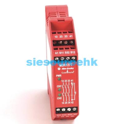
6. Real-world Troubleshooting & LED Diagnostic Status
The faceplate of the Guardmaster 440R relay contains four diagnostic LEDs that dramatically reduce troubleshooting time when a fault occurs in the field.
| PWR / Fault LED | IN1 LED | IN2 LED | OUT LED | System Status Description | Practical Troubleshooting Action |
|---|---|---|---|---|---|
| Green | Green | Green | Green | Normal operation. Safety loop is active and healthy. | None. Safety outputs 13/14 and 23/24 are closed. |
| Green | Off | Off | Off | Inputs open. E-stop is pressed or gate is open. | Release emergency stop or close safety gate. Check 24V loops. |
| Green | Green | Off | Off | Input channel imbalance or single-channel fault. | Check NC contact 2 of the E-stop. Verify S21-S22 wire continuity. |
| Green | Off | Green | Off | Input channel imbalance or single-channel fault. | Check NC contact 1 of the E-stop. Verify S11-S12 wire continuity. |
| Flashing Red (2-flash cycle) | Off | Off | Off | Cross-fault detected between S11/S12 and S21/S22 loops. | Check wiring for a short between Channel 1 and Channel 2 wires. |
| Flashing Red (3-flash cycle) | Off | Off | Off | Rotary switch configuration mismatch. | Check that the rotary dial positions match the wired inputs and reset type. Power cycle to apply. |
| Flashing Red (4-flash cycle) | Green | Green | Off | Feedback loop failure (EDM fault at terminal S34). | Check downstream contactors K1/K2. Verify auxiliary NC contacts are not welded. |
| Solid Red | Off | Off | Off | Non-recoverable internal hardware or processor fault. | Verify supply voltage is clean 24V DC. If fault persists, replace the relay. |
By utilizing this structured guide and terminal diagnostic matrices, electrical system integrators can reliably wire, commission, and troubleshoot the Allen-Bradley 440R safety relay, ensuring continuous safety compliance and maximum machinery uptime.
Technical & Application FAQs
Q1:What is the difference between S34 Monitored Manual Reset and Automatic Reset on the Allen-Bradley 440R?
Monitored Manual Reset (wired via terminal S34) requires the safety circuit to detect a transition from open to closed and back to open (falling edge) of the reset button before activating the safety outputs. This prevents startup lockouts or machine re-start if the reset button is permanently welded, jammed, or held down. Automatic Reset immediately closes the safety output contacts as soon as the input loops (S12/S22) are closed and healthy, which is only safe if another safety measure prevents access to the hazard zone.
Q2:How do you wire a dual-channel E-Stop to a 440R-D22R2 relay for Category 4 / PL e protection?
To achieve Category 4, you must wire the two independent NC contacts of the E-Stop button using separate test pulses. Connect the source test output S11 to the first NC contact and return it to input terminal S12 (Channel 1). Connect the second test source S21 to the other NC contact and return it to S22 (Channel 2). This dual-loop circuit ensures that a short-circuit between channels, or a short-circuit to 24V DC, is immediately detected by the relay’s internal processor as a cross-fault, triggering a safe shutdown.
Q3:What does a flashing red Power/Fault LED on an Allen-Bradley 440R relay indicate?
A flashing red PWR/Fault LED indicates a recoverable or non-recoverable internal fault or configuration error. The flashing rate represents specific diagnostics: a 2-flash cycle indicates a cross-fault between input channels; a 3-flash cycle signifies a configuration mismatch (e.g., rotary switch does not match current wiring); a 4-flash cycle points to a feedback loop fault (external contactor welded or stuck closed); and a solid red LED typically indicates a hardware failure requiring unit replacement.
Q4:Can I connect active semiconductor OSSD outputs, such as from safety light curtains, directly to the 440R safety relay?
Yes, Allen-Bradley Guardmaster 440R safety relays support direct connection of active OSSD semiconductor outputs. The rotary switch on the relay must be configured to the appropriate mode (such as OSSD Input mode). Because the light curtain generates its own self-monitoring test pulses, you must NOT connect the safety relay’s test pulse outputs (S11/S21) to the light curtain’s outputs. Instead, connect the OSSD 1 and OSSD 2 wires directly to the S12 and S22 safety input terminals, and reference them to a common ground.
Q5:What is the purpose of S52 and S44 terminals on GSR safety relays?
The S52 terminal is typically used as a common circuit control or auxiliary sensor power output, while the S44 terminal is a specialized signal line used for cascade configurations, expansion relay gating, or multi-unit synchronization. On specific models like the 440R-D22R2, S44 allows single-wire safety cascading to link multiple relays together in a unified safety control architecture.