



Blog
Siemens 3RV2021-1HA15 Specs: 5.5–8A Motor Protection Circuit Breaker Guide

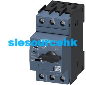
The Siemens 3RV2021-1HA15 is a SIRIUS 3RV2 motor protection circuit breaker designed for three-phase motor circuits requiring an adjustable overload setting of 5.5–8 A. It features a Class 10 thermal trip characteristic, a 104 A instantaneous short-circuit release, an S0 frame, and screw terminals. The device also includes a transverse auxiliary switch with one normally open and one normally closed contact. Its selection depends on motor rated current, starting characteristics, and the available short-circuit protection at the installation point.
Siemens 3RV2021-1HA15 Technical Specifications
The 3RV2021-1HA15 combines thermal overload protection, magnetic short-circuit protection, and manual switching in one three-pole device. Its 5.5–8 A adjustment range is the primary parameter for determining motor suitability.
| Specification | Details |
|---|---|
| Manufacturer | Siemens |
| Product family | SIRIUS 3RV2 |
| Complete model number | 3RV2021-1HA15 |
| Product type | Motor protection circuit breaker |
| Frame size | S0 |
| Main circuit poles | 3 |
| Overload release adjustment range | 5.5–8 A |
| Trip characteristic | Class 10 |
| Instantaneous short-circuit release | 104 A |
| Terminal connection | Screw terminals |
| Auxiliary contact configuration | 1 NO + 1 NC, transverse-mounted |
| Rated operational voltage | 20–690 V AC |
| Rated operational current | 8 A |
| AC-3 operational current at 400 V | 8 A |
| AC-3 motor power at 400 V | 3 kW |
| Rated insulation voltage | 690 V |
| Rated impulse withstand voltage | 6 kV |
| Degree of protection | IP20 |
| Operating ambient temperature | -20°C to +60°C |
| Maximum installation altitude | 2,000 m under specified conditions |
| Dimensions (W × H × D) | 45 × 97 × 97 mm |
| Net weight | Approximately 372 g |
Source: Siemens official 3RV2021-1HA15 datasheet. Electrical ratings and short-circuit performance depend on operating voltage and the specified installation conditions.
How Does the 5.5–8A Motor Protection Range Work?
The adjustable thermal release protects motors against sustained excessive current. The 3RV2021-1HA15 provides a setting range from 5.5 A to 8 A, allowing the protection setting to be matched to the motor’s rated current.
For example, a three-phase motor with a nameplate current of 7.2 A falls within the adjustment range. An appropriate setting can be selected according to the motor data and applicable protection requirements.
A motor rated at 4.5 A falls below the available range, while a motor rated at 9 A exceeds it. Neither should be forced into this model’s adjustment range. A suitably rated motor protection breaker should be evaluated instead.
Motor power alone is not sufficient for selecting the breaker. Rated current varies with motor voltage, efficiency, power factor, and operating conditions. The motor nameplate should therefore be the starting point for selection.
What Does the 104A Short-Circuit Release Mean?
The 104 A value is the instantaneous magnetic short-circuit release threshold. When the detected fault current reaches the specified release conditions, the magnetic mechanism initiates rapid circuit interruption.
This function is different from thermal overload protection:
- Thermal release: Responds to sustained overcurrent that can cause motor overheating.
- Magnetic release: Responds to high short-circuit current and initiates rapid interruption.
Importantly, 104 A is not the breaker’s short-circuit breaking capacity. Engineers must separately verify the rated ultimate breaking capacity (Icu) and service breaking capacity (Ics) at the actual system voltage.
For reference, published Siemens technical data lists the following short-circuit ratings under specified AC conditions:
| Voltage | Rated service breaking capacity (Ics) | Rated ultimate breaking capacity (Icu) |
|---|---|---|
| 240 V AC | 100 kA | 100 kA |
| 400 V AC | 100 kA | 100 kA |
| 500 V AC | 42 kA | 42 kA |
| 690 V AC | 4 kA | 6 kA |
These values must be interpreted together with the applicable network configuration, upstream protection, and installation fault level. They should not be applied indiscriminately to every motor starter arrangement.
Why Class 10 and Phase-Failure Protection Matter
The Class 10 characteristic describes the thermal overload trip behavior under specified test conditions. It is relevant when evaluating motor starting because motors typically draw higher current during acceleration than during normal operation.
Class 10 does not mean the breaker always trips after exactly ten seconds. Actual trip behavior depends on current magnitude, duration, thermal state, and the manufacturer’s time-current characteristics.
The 3RV2021-1HA15 also supports phase-failure-sensitive motor protection. In a three-phase system, losing one phase can cause current imbalance and overheating in the remaining phases.
This function is particularly relevant to pumps, fans, and production equipment where a motor may continue operating under abnormal phase conditions. The correct protection setting and installation must still follow the manufacturer’s instructions.
Applications in Industrial Motor Control
The 3RV2021-1HA15 can be considered for three-phase motor circuits with rated currents within its 5.5–8 A adjustment range.
- Conveyor equipment: Protection for small conveyor motors in production and material handling systems.
- Industrial fans: Motor protection in ventilation and air-handling equipment.
- Pump systems: Protection for appropriately rated water pumps and process pumps.
- Processing machinery: Protection for auxiliary motors in mixers and other industrial equipment.
The application must also satisfy the breaker’s voltage, starting, fault-current, and coordination requirements. A suitable current range alone does not guarantee that the device is appropriate for a particular motor circuit.
Auxiliary Contacts and Contactor Coordination
The 3RV2021-1HA15 includes a transverse auxiliary contact arrangement with one NO and one NC contact. These contacts provide additional switching signals for control and monitoring circuits.
For example, the auxiliary contacts can be incorporated into a PLC monitoring circuit to indicate the protective device’s operating state. The exact signal behavior should be checked against the wiring diagram and contact operating sequence.
In a conventional motor starter, the circuit breaker may be combined with a separate contactor. The breaker provides motor protection, while the contactor handles routine switching of the motor supply.
For related switching equipment, see the Siemens 3RT6015-1AN21 power contactor. This is a related SIRIUS component, not an automatically approved pairing with the 3RV2021-1HA15. The appropriate combination must be confirmed using Siemens coordination tables and the actual motor application.
How to Select a Replacement for 3RV2021-1HA15
When replacing an existing motor protection breaker, matching the product appearance or frame size is not enough. The complete electrical and mechanical configuration must be checked.
- Confirm the motor current: Verify that the required protection setting falls within 5.5–8 A.
- Check the trip characteristic: Confirm that Class 10 is appropriate for the motor’s starting conditions.
- Verify short-circuit ratings: Compare Icu and Ics against the prospective fault current and operating voltage.
- Inspect auxiliary contacts: Confirm that the existing control circuit requires 1 NO + 1 NC transverse auxiliary contacts.
- Check terminals and dimensions: Verify screw connections, S0 mounting compatibility, and available panel space.
- Review contactor coordination: If the breaker operates with a contactor, verify the approved starter combination.
For comparison, the Siemens 3RV2021-1BA15 motor protection breaker guide covers a lower 1.4–2 A adjustment range. The Siemens 3RV2021-4NA15 guide covers a higher 23–28 A range. These comparisons demonstrate why current range must be checked before selecting a replacement.
What Should Buyers Check Before Ordering?
For maintenance and spare-parts purchasing, provide the complete model number rather than describing the device only as a Siemens motor protection breaker.
Before requesting a quotation, prepare:
- Complete part number: 3RV2021-1HA15.
- Required quantity.
- Motor nameplate current and operating voltage.
- Existing contactor or motor starter reference, if applicable.
- Required auxiliary contact configuration.
- Product condition requirements and delivery destination.
You can also explore the Siesource industrial automation product catalogue for related Siemens control components. If you need this exact model, provide the full reference and application details through the Siesource contact page so the required configuration can be checked before ordering.
Frequently Asked Questions
What is the current adjustment range of Siemens 3RV2021-1HA15?
The adjustable thermal overload release range is 5.5–8 A. The setting should be based on the motor’s nameplate current and applicable protection requirements.
What is the short-circuit release of 3RV2021-1HA15?
Its specified instantaneous magnetic short-circuit release threshold is 104 A. This value is different from the rated short-circuit breaking capacity.
What does Class 10 mean on this Siemens breaker?
Class 10 describes the overload trip characteristic under defined test conditions. The actual trip time depends on the current magnitude, duration, and thermal state.
Does the 3RV2021-1HA15 include auxiliary contacts?
Yes. This model includes a transverse auxiliary contact arrangement with one normally open and one normally closed contact.
Can the 3RV2021-1HA15 protect every 8 A motor?
Not automatically. Although 8 A is the upper limit of its adjustment range, voltage, starting characteristics, fault level, coordination, and installation conditions must also be evaluated.
Conclusion
The Siemens 3RV2021-1HA15 is an S0-size SIRIUS motor protection circuit breaker with a 5.5–8 A adjustable overload range, a 104 A instantaneous magnetic release, and Class 10 protection. Its screw terminals and 1 NO + 1 NC auxiliary contacts make it suitable for evaluating specific industrial motor starter configurations. Before purchasing or replacing the device, verify the motor nameplate, short-circuit breaking requirements, auxiliary contact arrangement, and complete starter coordination.